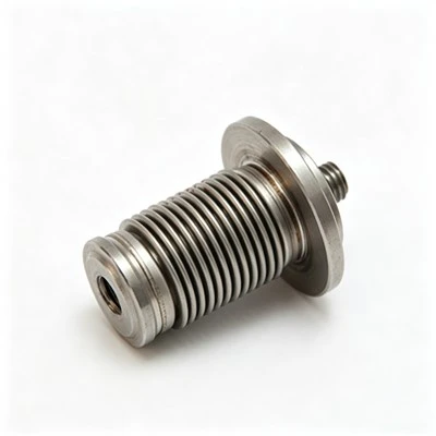
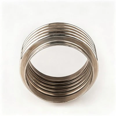
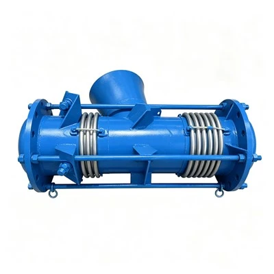
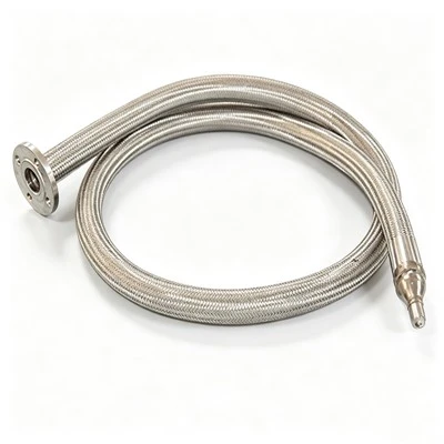
Stiffness: The load required to produce a unit displacement in a metal bellows or other elastic element is called the element's stiffness, usually denoted by "K". If the elastic characteristics of the element are nonlinear, the stiffness is no longer constant but changes with increasing load. For bellows-type elastic elements used in general engineering, the stiffness tolerance is limited to +/- 50%. Bellows stiffness is classified into axial stiffness, bending stiffness, and torsional stiffness according to the nature of the load and displacement. In bellows applications, the vast majority of loads are axial loads, and the displacement is linear. The following are some of the main methods for calculating the axial stiffness of bellows:
1. Energy method for calculating bellows stiffness
2. Empirical formula for calculating bellows stiffness
3. Numerical method for calculating bellows stiffness
4. EJMA standard stiffness calculation method
5. Japanese TOYO stiffness calculation method
6. American KELLOGG (new method) stiffness calculation method
Besides the above six stiffness calculation methods, there are many other methods for calculating stiffness abroad, which will not be introduced here. Chinese mechanics researchers have conducted extensive research and experimental analysis on bellows, achieving fruitful results. The most important research methods include:
(1) Perturbation method
(2) Initial parameter method of numerical integration
(3) Integral equation method
(4) Perturbation finite element method. All of these methods can provide relatively accurate calculations of bellows. However, due to the application of advanced theoretical and computational mathematics, their engineering application is somewhat difficult and they are hard to master, requiring further popularization and promotion.
Stiffness Calculation When Metal Bellows are Used in conjunction with Helical Springs
When high stiffness is required during use, but the stiffness of the metal bellows itself is relatively low, a cylindrical helical spring can be considered to be placed inside or outside the bellows. This not only improves the stiffness of the entire elastic system but also greatly reduces the error caused by hysteresis. The elastic performance of this system mainly depends on the characteristics of the spring and the stability of the effective area of the bellows.
Bending Stiffness of Bellows
Stress Calculation of Bellows
As an elastic sealing component, a metal bellows must first meet the strength requirement, meaning its maximum stress does not exceed the allowable stress under given conditions. The allowable stress can be obtained by dividing the ultimate stress by a safety factor. Depending on the bellows' working conditions and usage requirements, the ultimate stress can be the yield strength, the critical stress at which the bellows becomes unstable, or the fatigue strength, etc. Calculating the maximum working stress of a bellows requires analyzing the stress distribution within the bellows wall.
The stress on a bellows is generated by the pressure in the system and the bellows' deformation. Pressure generates circumferential stress on the bellows, while radial membrane and bending stresses are generated at the sidewalls, troughs, and crests of the wave. Thin shells that cannot resist bending are sometimes called membranes, and the stress calculated by neglecting bending is called membrane stress. Radial membrane stress and bending stress are generated when the bellows deform. When bellows are in operation, some bear internal pressure and some bear external pressure. For example, bellows expansion joints and metal hoses mostly bear internal pressure, while bellows used for valve stem seals generally bear external pressure. This analysis mainly focuses on the stress of bellows under internal pressure. The ability of bellows to withstand external pressure is generally higher than their ability to withstand internal pressure. With the widespread application of bellows, extensive analysis, research, and experimental verification of bellows stress have been conducted, resulting in many calculation formulas, programs, and charts for engineering design. However, some methods are inconvenient to use due to their complex charts or programs, while others make overly simplified or idealized assumptions, making it difficult to guarantee safe and reliable use. Many methods have not been accepted by the engineering community. Therefore, only a few methods truly meet practical requirements. Two commonly used methods are as follows:
Numerical Method for Calculating Bellows Stress
This method assumes that all bellows are under the same conditions, and only studies a single half-wave of the bellows during the calculation. Thus, the end bellows are not considered in the study, although the boundary conditions of the end bellows are different from those of the middle bellows. The numerical method is based on E... The solution is derived from the nonlinear equations proposed by Lesner for the axially symmetrical deformation of a thin-walled shell of revolution with varying wall thickness. In deriving the E. Lesner equations, general assumptions of thin-shell theory are applied, including: the assumption that the thickness is very small compared to the principal radii of the shell's curvature; and the assumptions of material homogeneity and isotropy. These assumptions also introduce certain errors into the calculations. This is because during the manufacturing of bellows, the rolling, drawing, and subsequent corrugating plastic forming of the billet cause anisotropy and non-uniformity in the material's mechanical properties.
Stress Calculation Method of the American EJMA
Effective Area Calculation of Bellows
The effective area is one of the basic performance parameters of a bellows. It characterizes the bellows' ability to convert pressure into concentrated force. In applications where bellows are used to convert pressure into concentrated force output, the effective area is a crucial parameter.
When bellows are used in force-balanced instruments, the stability of its effective area directly affects the instrument's accuracy. Therefore, in such applications, not only is a reasonable effective area required, but the effective area must also remain unchanged during operation regardless of working conditions.
1. Concept and Changes in Effective Area
The effective area is an equivalent area on which pressure exerted will produce an equal axial force. Generally, the effective area of a bellows decreases with increasing internal pressure and increases with increasing external pressure.
2. Effective Volumetric Area of a Bellows
The ratio of the volume change of a bellows under external force or pressure difference to the corresponding change in effective length is called its effective volumetric area.
3. Calculation of the Effective Area of a Bellows
The requirements for and calculation methods of the effective area of a bellows depend on its intended use. If the bellows is used as an elastic seal or for pipeline thermal compensation, the effective area is only significant for calculating the axial force during bellows forming and the thrust in the system. There is often a difference between the calculated and measured effective area of a bellows. Generally, calculating the effective area using a specific formula is sufficient.
When bellows are used in force balancing instruments and applications requiring pressure to be converted into force, their effective area must be accurately determined, requiring individual measurements.
Sensitivity: The displacement of a metal bellows and other elastic elements under a unit load is called the element's sensitivity. Stiffness and sensitivity are the main functional parameters of bellows and other elastic elements, but they are two different ways of expressing the same performance characteristic. For different situations, either parameter can be used for ease of analysis.
Effective Area: For elastic elements that realize pressure-force or force-pressure conversion, another important functional indicator is the effective area. The effective area refers to the magnitude of the concentrated force that the elastic element can convert when its displacement is zero under a unit pressure.
Service Life: Elastic elements operate in two states: one is working under certain load and displacement conditions, maintaining a constant or minimally changing load and displacement, called static operation; the other is when the load and displacement continuously and cyclically change, and the element is in a cyclic operating state. Due to the different operating states, the damage or failure modes of the element also differ. Instrument elastic sensitive elements operate within their elastic range, essentially in a static operating state, and have a very long service life, generally reaching tens of thousands to hundreds of thousands of cycles. Bellows-type components used in engineering sometimes operate within an elastic-plastic range or under alternating stress, with a lifespan of only a few hundred to a thousand cycles. When components are used in cyclic operation, an allowable working life must be specified, including the number of cycles, time, and frequency.
The rated life of an elastic element is the expected service life determined during the element's design, requiring that the element not experience fatigue, damage, or failure within this period.
Sealing Performance: Sealing performance refers to the ability of an element to prevent leakage under a certain internal and external pressure difference. Bellows-type components operate with their internal cavity filled with gas or liquid media under pressure, therefore, sealing performance must be guaranteed. Sealing performance testing methods include pneumatic sealing tests, leakage tests, liquid pressurization tests, and leak detection using soapy water or a helium mass spectrometer.
Natural Frequency: Elastic elements used in industry often operate in environments with a certain degree of vibration. Some components are used as vibration isolation parts and are themselves under vibration conditions. For elastic elements used under special conditions, it is essential to prevent the element's natural frequency (especially the fundamental frequency) from being close to the frequency of any vibration source in the system to avoid resonance and damage. Bellows components are widely used in various fields. To avoid damage to the bellows' resonant surfaces, the bellows' natural frequency should be lower than the system's vibration frequency, or at least 50% higher.
Operating Temperature: The operating temperature range of metal bellows components is wide and is generally specified before the design and manufacture of the elastic element. Some special-purpose bellows have internal cavities that can withstand liquid oxygen (-196℃) or even lower temperatures like liquid nitrogen, with pressure resistance up to 25MPa. Large bellows expansion joints (sometimes with nominal diameters exceeding 1m) used for pipeline system connections require pressure resistance of 4MPa, temperature resistance of 400℃, and a certain degree of corrosion resistance. The temperature adaptability of the elastic element depends on the temperature resistance of the elastic material used. Therefore, selecting an elastic material with appropriate temperature performance parameters based on the operating temperature range of the elastic element is essential for manufacturing qualified bellows components.